Second Proposed Bus Turnaround Site Archaeological Report, Block 34Originally entitled: "Recent Archaeological Investigations at the Site of the Second Proposed Bus Turnaround, Block 34"
Colonial Williamsburg Foundation Library Research Report Series - 1619
Colonial Williamsburg Foundation Library
Williamsburg, Virginia
1990
RECENT ARCHAEOLGICAL INVESTIGATIONS AT THE SITE OF THE SECOND PROPOSED BUS TURNAROUND, BLOCK 34.Carl:
Best Wishes,
Steve
Department of Archaeology
Office of Excavation and Conservation
Colonial Williamsburg Foundation
May 31, 1985
TABLE OF CONTENTS
| LIST OF FIGURES | 3 |
| LIST OF TABLES | 5 |
| ACKNOWLEDGMENTS | 6 |
| INTRODUCTION | 7 |
| HISTORICAL AND ARCHAEOLOGICAL BACKGROUND | 8 |
| Prehistoric Occupation | 8 |
| Middle Plantation: 17th-century Occupation | 8 |
| Williamsburg: 18th-century Occupation | 9 |
| Williamsburg: 19th and 20th-century Occupation. | 14 |
| EXCAVATION PROCEDURES | 19 |
| RESULTS OF THE TEST EXCAVATIONS | 22 |
| Test Excavation Units 1 and 3 | 22 |
| Test Excavation Unit 2 | 34 |
| Shovel Test Pit 1 | 36 |
| Shovel test Pit 2 | 42 |
| SUMMARY | 45 |
| RECOMMENDATIONS FOR MITIGATION | 46 |
| REFERENCES CITED | 47 |
| APPENDIX 1: THE ARTIFACT INVENTORY | 51 |
| Figure 1. Plan of the proposed Bus Turnaround 2 Project, Block 34 | 7 |
| Figure 2. Hypothetical conception of the 17th-century horse path and building foundations located in Middle Plantation | 10 |
| Figure 3. Plan of the City of Williamsburg in the late 18th-century | 11 |
| Figure 4. Planview map of the 18th-century chimney foundation found during the 1947 archaeological excavations in the southeast corner of Block 34 | 12 |
| Figure 5. Photograph of the 18th-century chimney foundation located in the 1947 archaeological excavations | 13 |
| Figure 6. Plan of Block 34 during the early 20th-century. Note the locations of the houses and associated outbuildings | 16 |
| Figure 7. Photograph showing the houses situated on Block 34 in 1927 | 17 |
| Figure 8. Photograph showing the houses situated on Block 34 in the 1930's after the reconstruction of the Palace | 18 |
| Figure 9. Location of the test excavation units with respect to the project area | 20 |
| Figure 10. General view of the project area from the Palace. Note the highlighted areas denote Bayberry Trees. The concrete pad is in the center of the photograph | 21 |
| Figure 11. General view of Test Excavation Units 1 and 3, facing north. Note the depression under the north arrow | 23 |
| 4 | |
| Figure 12. General view of Test Excavation Units 1 and 3, facing south toward Scotland Street. Note the depression in the left foreground. Horizons A, B, and C, and Features 1, 1a, 2, and 3 are denoted by tags | 24 |
| Figure 13. Profile of the well fill, Feature 4: 1.55' to 2.0' BAL, Feature 5: 2.5' to 3.0' BAL. Photo shows the north wall of Unit 3, and the position of the ground surface | 25 |
| Figure 14. Profile map of the south wall of Units 1 and 3, partially excavated | 27 |
| Figure 15. Planview of Units 1 and 3, partially excavated | 28 |
| Figure 16. Planview map of Units 1 and 3, partially excavated | 29 |
| Figure 17. Profile map of the north wall of Units 1 and 3, partially excavated | 31 |
| Figure 18. Profile of the south wall of the well, Feature 1a. Note shell and sand mortar bonding the upper four courses of brick | 32 |
| Figure 19. Profile of the south wall of Test Excavation Unit 2. Note a portion of Feature B-1 is evident in the right hand corner of the unit | 37 |
| Figure 20. Profile map of the south wall, profile map of the west wall, and planview map of the top of Feature B-1, Test Excavation Unit 2 | 38 |
| Figure 21. Profile of the south wall of Shovel Test Pit 1 | 40 |
| Figure 22. Profile maps of the south and west walls of Shovel Test Pit 1 | 41 |
| Figure 23. Profile of the south wall of Shovel wall of Shovel Test Pit 2 | 43 |
| Figure 24. Profile maps of the south and west walls of Shovel Test Pit 2 | 44 |
| Table 1. List of title changes for Colonial Lot 179, Block 34 | 15 |
ACKNOWLEDGMENTS
Fieldwork was primarily conducted by the author, with the assistance of Nathanial Smith and Greg Brown on two occasions.
Linda Derry, Andrea Foster, and Patricia Samford provided excellent research briefings. Patricia Samford conducted additional background research on the property owners on Block 34.
Joane Bowen conducted the faunal analysis for the project.
Edward Spencer and Gertrude Daversa were helpful with local oral histories.
INTRODUCTION
Plans for the construction of a second proposed bus turnaround at Block 34 are currently under consideration. The project area is located in the southeast corner of the Palace Pasture, northwest of the intersection of Scotland and North England Streets (Figure 1). Basically, the planned turnaround will extend from the intersection of the Colonial Parkway access road and North England Street, west and then south around the knoll in the southeast corner of pasture, connecting with Scotland Street.
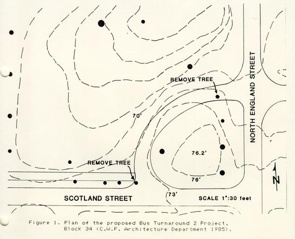 Figure 1. Plan of the proposed Bus Turnaround 2 Project, Block 34 (C.W.F. Architecture Department 1985).
Construction of the turnaround will entail both grading and filling operations in the project area (Hollowell 1985, personal communication). These land moving operations will be focused on the east, north, and west perimeters of the extant knoll. In some areas it appears that grading will remove approximately two feet of soil in order to conform to the existing street grades, particularly at the intersection of the proposed turnaround and North England Street. In addition, at least two trees are slated for removal, one tree is located at the proposed intersection of the turnaround and North England Street, while the other tree is situated at the proposed intersection with Scotland Street (C.W.F. Architecture Department 1985) (Figure 1). Hence, it appears that these construction activities will adversely affect the existing topography and general setting of this particular area.
HISTORICAL AND ARCHAEOLOGICAL BACKGROUND
Prehistoric Occupation
Environmental and ecological conditions during the terminal Wisconsin glaciation (ca. 10,000 years ago) and up through the 17th century were favorable for settlement and resource exploitation by the Amerind populations that inhabited the peninsula. Numerous archaeological investigations (e.g., Virginia Research Center for Archaeology or the Archaeological Society of Virginia) have produced conclusive evidence of successive occupations from the terminal Paleo-Indian, Archaic, and Woodland periods. Recently, prehistoric remains have been found in the vicinity of Williamsburg during the Camp Peary West Parcel Archaeological Survey (Alexandrowicz n.d.) and the Route 199 Archaeological Survey (Hunter and Higgins n.d.). However, no evidence has been found to verify the prehistoric occupation in this specific project area during our investigation.
Middle Plantation: 17th-century Occupation
Patricia Samford (1985) has indicated that following the massacre of 1622 the Middle Plantation palisade, which connected College Landing and Capitol Landing, probably was constructed across this general area. Likewise, Frank Grimsly (1985, personal communication), suggested that the palisade might have been situated in this area, based on the independent research that he has undertaken over the past few years. A portion of the palisade was found lying north of the Historic Area during an archaeological testing 9 project for the Second Street extension (Hunter, Samford, and Brown et al. 1984). Unfortunately, the present archaeological excavation conducted at the proposed bus turnaround locus has not recorded the remains of the palisade.
Habitation sites attributed to the Middle Plantation occupation are unknown in this project area. James Knight (1942) produced a map that illustrated the approximate location of a 17th-century horse path that went through Williamsburg, as well as the location of several probable 17th-century building foundations (Figure 2). The proveniences of these foundations were outside the immediate project area. Hence, a paucity of archival and archaeological data prohibits further discussion of the pre-Williamsburg era occupation of this area.
Williamsburg: 18th-century Occupation
One structure was depicted on the Frenchman's Map (1782) in close proximity to this specific project area (Figure 3). Andrea foster (1984), Linda Derry (1985), and Patricia Samford (1985) have all noted that the rectangular building was located at the northern end of North England Street, on Colonial Lots 179 and 180, in the 18th-century. Other contemporary buildings in this vicinity were situated at a distance from the project area and appear to be associated with the Palace complex.
Archaeological excavations conducted in 1942 in the property northwest of the North England and Scotland Street intersection did not encounter the remains of any 18th-century foundations (Derry 1985, Samford 1985). The area directly adjacent to the intersection (southeast corner of Block 34) was not tested at that time for some unknown reason.
In 1947 James Knight conducted excavations in the properties directly adjacent to the intersection of North England and Scotland Street, in the southeast corner of Block 34 (Knight 1947a). Although the Frenchman's Map (1782) does not show a building within this area, the test excavations conducted by James Knight produced positive results. Knight's excavations culminated in the identification of an apparent 18th-century chimney foundation (Figures 4 and 5). The foundation was located 71' 10" north of Scotland Street and 39' 6 ¾" west of North England Street (Knight 1947b). This chimney feature is the only documented remnant of the 18th-century occupation within the project perimeters.
 Figure 2. Hypothetical conception of the 17th-century horse path and building foundations located in Middle Plantation (Knight 1942).
 Figure 3. Plan of the City of Williamsburg in the late 18th-century (Frenchman's Map 1782).
 Figure 4. Planview map of the 18th-century chimney foundation found during the 1947 archaeological excavations in the southeast corner of Block 34 (Knight 1947b).
 Figure 5. Photograph of the 18th-century chimney foundation located in the 1947 archaeological excavations (Knight 1947c).
Williamsburg: 19th and 20th-century Occupations
A map entitled "Plan of the City of Williamsburg from the...Benj. Bucktrout August 1800" lists the Peachy family as owners of Colonial Lot 179 (Bucktrout 1800). The southern portion of the lot is within the project area. This property was retained by that family until 1845. After that time the land was sub-divided and changed hands until it was purchased by W. A. R. Goodwin in 1928 (Samford 1985). Refer to Table 1 for a list of property owners of Lot 179. Figure 6 illustrates the spatial configuration of the properties, as well as the location of three houses and related outbuilding structures as they appeared in 1929 (Waddill 1929). These houses are evident in a photograph taken in 1927 (Figure 7), and in a photograph taken during the 1930's restoration of the Governor's Palace (Figure 8). All of these residences continued to be rented by Afro-American families after their purchase by the Williamsburg Holding Corporation (Deversa 1985, personal communication). The last of the structures was eventually razed by September 1940 (Crutchfield Rent File 1929-1933; Harris House General File 1940).
As stated above, the 1942 archaeological excavations conducted in the major portion of Block 34, as well as the 1947 excavations undertaken in the southeast corner of Block 34 (Knight 1947a, b, c) were focused on the 18th-century cultural components, Thus the 19th and 20th-century components were not recorded, until now.
During the hiatus between 1947 and 1985 the portion of Block 34 between the Palace and the southeast corner was used as a parking lot and pasture. In the 1960's, the central portion of the block was modified and used as an employee and visitors parking lot (Spencer 1985, personal communication). Later, during the 1970's and through the present, the property has functioned as a horse pasture.
Subsequent archaeological investigations in Block 34 were not undertaken until 1985. In February, archaeological monitoring of a construction trench for the placement of an electric line in the Palace Pasture produced interesting results (Alexandrowicz 1985a). Stratigraphic profiles attested to the 19th and 20th-century occupations in the southeast corner of the block. In addition, a concentrated matrix of building debris was found directly adjacent to Bus Stop #9, on the west side of North England Street. The brick rubble most likely represented the rubble of the eastern house situated on the Joanna B. Harris Estate, as detailed by Waddill in 1929 (Figure 6).
Chain of Title for Lot 179
| 1845 | Land conveyed to Jacob Shelton and John Maupin by the executor of Mary and William Peachy. |
| 1846 | Shelton and Maupin conveyed land to Robert Armistead. Sometime during this period Armistead extended Chesapeake Avenue (N. England Street) through the property. |
| 1877 | Armistead conveyed land to Alexander Dunlop. |
| 1889 | William Morecock was appointed Special Commissioner and was directed to convey this land in the suit of John A. W. Jones against Alexander Dunlop. |
| May 1889 | Morecock conveyed land to John Carey. |
| June 1889 | John and Sarah Carey conveyed to John M. Dawson. |
| 1907 | Land involved in a Chancery suit. |
| 1907 | Joanna B. Harris, unmarried, was conveyed land by a Deed of Trust. |
| 1916 | Joanna Harris, widow, conveyed land by Deed of Trust. |
| 1920 | Joanna Harris, deceased, left land to son Samuel Harris. |
| 1924 | Samuel Harris et al. conveyed land to Letty Warburton. |
| 1928 | Letty Warburton and T. W. Crutchfield (who apparently owned the property but did not yet possess the title to the land) conveyed the property to W. A. R. Goodwin. |
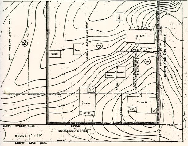 Figure 6. Plan of Block 34, southeast corner, during the early 20th-century. Note the locations of the houses and associated outbuildings (Waddill 1929).
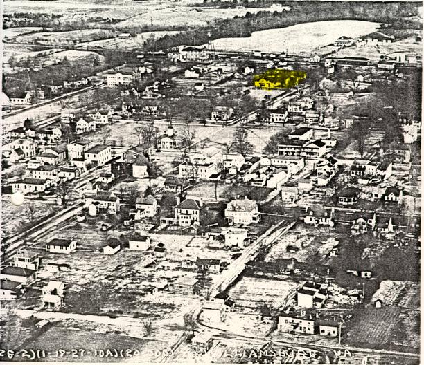 Figure 7. Photograph showing the houses situated on Block 34, southeast corner, in 1927 (C.W.F. Audio-visual Department, Negative No. 79-1409 1927).
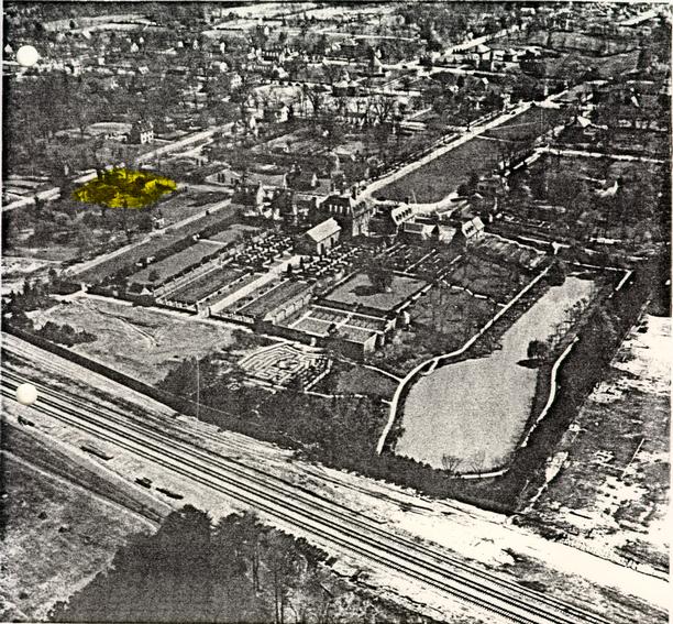 Figure 8. Photograph showing the houses situated on Block 34, southeast corner, in the 1930's after the reconstruction of the Palace (C.W.F. Audio-visual Department Negative No. 79-1265 n.d.).
EXCAVATION PROCEDURES
Parameters for the project area were determined from the project map that was supplied by the Architecture Department (Hollowell 1985) (Figure 1). Project boundaries were staked in the field in order to ascertain the extent of the area that was to be tested.
A site datum was established at the southeast corner of the Palace Pasture fenceline (Figure 9). Fencelines running north/south and east/west from the datum were used as baselines. Proveniences for the test excavation units and shovel test pits were established from these baselines. Granite curbing and their respective axes along the north margin of Scotland Street and along the western border of North England Street served as permanent landmarks for the datum. In addition, these curbs served as reference points when measurements were taken to relocate the 18th-century chimney foundation that was found in 1947 (Knight 1947b).
Time, money, and scheduling would not permit lengthy test excavations. Therefore, we strived to obtain the most information available, without expending out limited resources. With this in mind the decision was made to perform test excavations at both ends, and in the center of the proposed turnaround. In choosing the exact location for the test units, variables such as surface scatters of artifacts, extant topographic and hydrologic characteristics, and vegetation (ground cover) were used. Initially, a pedestrian survey of the project area located the remains of a concrete pad, as well as scattered building debris on the northwestern margin of the knoll, near the curve in the proposed roadway. Two clusters of Bayberry trees, situated in the midst of lush ground vegetation, were visible (Figure 10). However, these clusters were in the central island that was not planned to be developed. A depression, filled with lush ground cover, was evident in the center of the eastern end of the proposed roadway. Topographically, this depression was on the northern border of the knoll, situated in the southeast corner of Block 34 (Figures 9 and 10). Thus we had two clues that something had occurred in this spot in the past and that this was a promising location to test. Likewise, these variables were incorporated into the research design used earlier this year during the Camp Peary West Parcel Archaeological Survey (Alexandrowicz n.d.).
Two types of test excavation units were used during the project. Test Excavation Units were 2.5 feet square, while the Shovel Test Pits were 1.5 feet square. Three Test Excavation Units, denoted 1, 2, and 3 were dug (Figure 9).
20
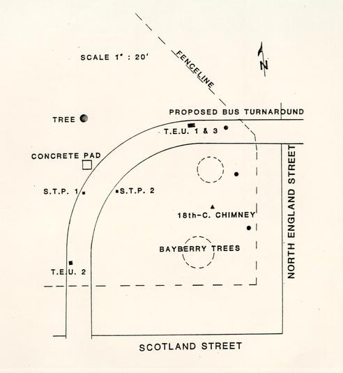 Figure 9. Location of the test excavation units with respect to the project area.
21
Figure 9. Location of the test excavation units with respect to the project area.
21
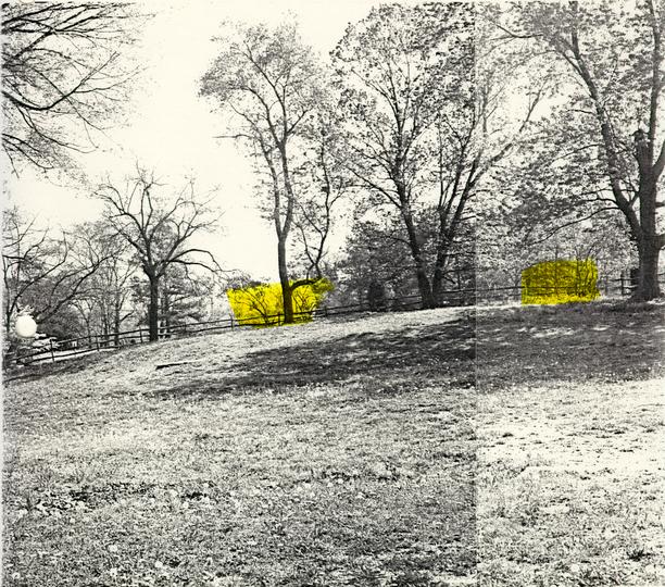 Figure 10. General view of the project area from the Palace. Note the highlighted areas denote Bayberry Trees. The concrete pad is in the left center.
22
Units 1 and 3 were contiguous, while Unit 2 was isolated. Shovel Test Pits 1 and 2 were placed 18.5 feet apart (Figure 9).
Figure 10. General view of the project area from the Palace. Note the highlighted areas denote Bayberry Trees. The concrete pad is in the left center.
22
Units 1 and 3 were contiguous, while Unit 2 was isolated. Shovel Test Pits 1 and 2 were placed 18.5 feet apart (Figure 9).
Methods of excavation included careful shovel scraping and troweling. Excavation was very meticulous and resulted in the location a well feature, and a well-head feature within a couple of inches of the ground surface, without any adverse damage to the feature. All soil was screened through 1/4 inch mesh screen.
Artifacts were separated by respective horizons in each unit (Appendix 1). Soil samples were obtained from individual horizons/features for lab analysis. Mapping techniques included standard planview (horizontal axis) and profile (vertical axis) mapping applications. In addition, an alternative mapping technique (Alexandrowicz 1985b) was used. All measurements were taken with tapes or rulers marked in tenths of feet increments. Azimuth readings or bearings were taken with a Silva (Ranger Model) pocket transit. Photographs were taken in both color. (35 mm.), as well as black and white (120 mm.) formats.
RESULTS OF THE TEST EXCAVATIONS
In general, the archaeological testing operation produced conclusive evidence of the 19th to 20th-century occupation of this portion of Block 34. Three contemporary 19th to 20th-century cultural features were recorded. They included a brick-lined well (Feature 1a), a well-head or building foundation (Feature 1), and a post hole (Feature 3). Feature 2 represented the late 19th to early 20th-century builders trench associated with Feature 1. Eighteenth-century artifacts recovered during the testing operation were found in disturbed and undisturbed contexts.
Test Excavation Units 1 and 3
As mentioned in EXCAVATION PROCEDURES, Test Unit 1 was placed at the edge of a ca. 4 ft. diameter depression (approximately one-half foot deep), located on the northern margin of the knoll, in the southeastern corner of Block 34 (Figure 11). Vegetation, primarily grass, was fairly sparse in the general area of the depression. However, the grass inside the depression was very lush and thick. This vegetation indicated a high moisture content in the soil and thus reflected an organic soil deposit. An initial perception or explanation of this surface anomaly was a possible well. In order to determine the constituent 23 elements of the feature lying within and outside the depression, Test Excavation Unit 1 was placed on the southwestern margin of the depression (Figure 11). Test Excavation Units 1 and 3 contained Horizons A, B, C, Feature 1, Feature 1a, Feature 2, Feature 3, Feature 4, and Feature 5 (Figures 12 and 13).
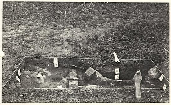 Figure 11. General view of Test Excavation Units 1 and 3, facing north. Note the depression under the north arrow.
 Figure 12. General view of Test Excavation Units 1 and 3, facing south toward Scotland Street. Note the depression in the left foreground. Horizons A, B, C, and Features 1, 1a, 2, and 3 are denoted by tags.
 Figure 13. Profile of the well fill, Feature 4: 1.55' to 2.0' BAL, Feature 4: 2.0' to 2.5' BAL, Feature 5: 2.5' to 3.0' BAL. Photo shows the north wall of Unit 3, and the position of the ground surface.
HORIZON A
Horizon A (Figures 12 and 14) consisted of a very dark brown (10 YR 2/2) (Munsell Color 1975), loamy sand. Artifacts recovered in this stratum included: cinders, bone, coal, macadam, brick, bog iron, gravel, shell, nails, ceramics, concrete, clinkers, mortar, wire, and glass (Appendix 1). Several 18th and 19th century artifacts were recovered. However, this horizon represented a topsoil that was deposited sometime after the destruction of the houses that were located in this vicinity of the block, ca. 1940 up to the present.
HORIZON B
Horizon B (Figures 12 and 14) consisted of a very dark brown (10 YR 2/2) (Munsell Color 1975), loamy sand. Inclusions in the soil were nodules of brownish yellow (10 YR 6/8) (Munsell Color 1975), loamy sand. The inclusions in this matrix differentiated it from the superimposed Horizon A. Artifacts that were extracted from Horizon B included: brick fragments, cinder, shell, gravel, ceramic, coal, clinker, gravel, mortar, nails, and glass (Appendix 1). Although the horizon contained 18th and 19th-century artifacts, this horizon represented the late 19th to early 20th century occupation grade in this area.
HORIZON C
Horizon C (Figures 12 and 14) consisted of a brownish yellow (10 YR 6/8) (Munsell Color 1975), loamy sand. Small brick fragments were evident in the soil and appeared to be intrusive from above. No artifacts were recovered from this horizon (Appendix 1), although the small brick fragments were noted. Horizon C appeared to represent a subsoil fill, which was redeposited in this location at an unknown time. Future excavations may aid us in dating this fill deposit.
FEATURE 1
Feature 1 appeared as an "L" shaped construction when it was initially encountered during the excavations. This feature (Figures 12, 15, and 16) was constructed of red colored (10 R 4/8) (Munsell Color 1975) bricks laid end to end (header to header) with the stretcher facets exposed on the interior and exterior of the feature. The bricks were single course in width. Several bricks were found with
27
 Figure 14. Profile map of the south wall of units 1 and 3, partially excavated.
28
Figure 14. Profile map of the south wall of units 1 and 3, partially excavated.
28
 Figure 15. Planview of Units 1 and 3, partially excavated.
29
Figure 15. Planview of Units 1 and 3, partially excavated.
29
 Figure 16. Planview map of Units 1 and 3, partially excavated.
30
patches of shell mortar affixed to them, indicating an 18th-century cultural affiliation, while other bricks exhibited sand mortar, a characteristic of 19th-century construction. The author concludes that these bricks were robbed or salvaged from another feature and re-used in the construction of this particular feature. Based on the juxtaposition of Feature 1 and Feature 1a, Feature 1 appeared to represent a well-head foundation that encompassed Feature 1a, the well. A brick and/or wooden well-head structure was probably built upon this brick foundation. Based on the artifacts recovered from the builders trench (Feature 2), which was directly associated with the well-head foundation, this feature was probably constructed during the late 19th to early 20th century. However, we must not ignore the possibility that the well-head foundation could have been constructed at an earlier date and later repaired during the late 19th to early 20th century.
Figure 16. Planview map of Units 1 and 3, partially excavated.
30
patches of shell mortar affixed to them, indicating an 18th-century cultural affiliation, while other bricks exhibited sand mortar, a characteristic of 19th-century construction. The author concludes that these bricks were robbed or salvaged from another feature and re-used in the construction of this particular feature. Based on the juxtaposition of Feature 1 and Feature 1a, Feature 1 appeared to represent a well-head foundation that encompassed Feature 1a, the well. A brick and/or wooden well-head structure was probably built upon this brick foundation. Based on the artifacts recovered from the builders trench (Feature 2), which was directly associated with the well-head foundation, this feature was probably constructed during the late 19th to early 20th century. However, we must not ignore the possibility that the well-head foundation could have been constructed at an earlier date and later repaired during the late 19th to early 20th century.
FEATURE 1a
Feature 1a, a brick-lined well, was encountered within the confines of Feature 1, the brick well-head (Figures 12, 15, and 16). Both features were located within one-half of a foot under the ground surface (Figures 12 and 17). The feature was constructed of brick, laid in stretcher courses, one course wide. This method of construction dates to the end of the 19th century in Williamsburg (Noel Hume 1969:23). Pale yellow (10 YR 7/4) (Munsell Color 1975) shell and sand mortar was used to bond the upper four courses of red (10 R 4/8) (Munsell Color 1975) brick, while the underlying courses were dry-laid (Figure 18). Although only a portion of the feature was excavated, the diameter was estimated to be four feet, based on the curvature of the construction, as well as the overall size of the surface depression (Figures 6 and 16). This well probably was constructed during the last quarter of the 19th century or the early 20th century, since it is directly associated with Feature 1, the well-head, as well as Feature 2, the builders trench.
Fill within the well was partially excavated (Figures 13 and 17) and resulted in the identification of two fill deposits, Feature 4 and Feature 5. The fill was excavated in one-half foot increments within each separate deposit, in order to maintain precise excavation control of the individual deposits. Feature 4 represented the uppermost layer of fill. The initial excavation increment of 1.55' to
31
 Figure 17. Profile map of the north wall of Units 1 and 3, partially excavated.
32
Figure 17. Profile map of the north wall of Units 1 and 3, partially excavated.
32
 Figure 18. Profile of the south wall of the well, Feature 1a. Note shell and sand mortar bonding the upper four courses of brick.
33
increment of fill were: brick fragments, mortar, concrete, gravel, clinker, cinders, charcoal, coal, shell, bone, nails, and glass (Appendix 1). Wire nails produced a "terminus post quem" (TPQ) of 1880 for the filling of the upper portion of the feature. In other words, the fill could have been deposited anytime after 1880.
Figure 18. Profile of the south wall of the well, Feature 1a. Note shell and sand mortar bonding the upper four courses of brick.
33
increment of fill were: brick fragments, mortar, concrete, gravel, clinker, cinders, charcoal, coal, shell, bone, nails, and glass (Appendix 1). Wire nails produced a "terminus post quem" (TPQ) of 1880 for the filling of the upper portion of the feature. In other words, the fill could have been deposited anytime after 1880.
The next excavation increment within the Feature 4 deposit was 2.0' to 2.5' BAL (Figure 13). It was composed of very dark brown (10 YR 2/2) (Munsell Color 1975), loamy sand, with brownish yellow (10 YR 6/8) (Munsell color 1975) mottles. Cultural material in the fill was represented by brick fragments, concrete, cinders, charcoal, slate, gravel, shell, clinker, nails, ceramic, and glass (Appendix 1). A fragment of "Depression Glass" located in this excavation increment narrows the date of deposition for this layer to the circa 1920's through the 1930's.
Feature 5, 2.5' to 3.0' BAL, was found directly under Feature 4, 2.0' to 2.5' BAL, and represented a separate fill horizon within the well (Figures 12 and 17). Feature 5 was composed of a mixture of very dark brown (10 YR 2/2) (Munsell Color 1975) and brownish yellow (10 YR 6/8) (Munsell Color 1975), loamy sand. Artifacts excavated in this horizon consisted of: brick fragments, bog iron, gravel, concrete, clinker, cinder, coal, charcoal, mortar, nails, shell, walnut shell, bone, ceramic, and glass (Appendix 1). Wire nails provided a "TPQ" of 1880 for the deposition of this horizon, although the layer could have been deposited any time after that date.
An interesting fact to note is that the City of Williamsburg passed an ordinance in 1923 which stipulated that all open wells, which incorporated buckets, chains or similar devices, were to be filled-in (Noel Hume 1969: 32). It may be that the residents of the lot at this time, Samuel J. Harris et al., heirs of the Joanna Harris estate (Foster 1984), filled the well in compliance with this regulation. This proposition is predicated on the recovery of the "Depression Glass" in Feature 4: 2.0' to 2.5' BAL, suggesting a date of deposition for the upper strata of approximately the 1920's through the early 1930's, or thereafter. However, we should not ignore the fact that the well could have been filled-in with different soil deposits during one final episode, anytime before September 1940.
FEATURE 2
Feature 2 was identified as a builders trench associated with the construction of the well-head (Feature 1) and well (Feature 1a) (Figures 12, 15, 16, and 18). The builders trench was composed of a black (10 YR 2/1) (Munsell Color 1975), sandy loam, with brownish yellow (10 YR 6/8) sandy 1oam mottles. Due to the brevity of the project this feature was not excavated. Instead, a soil sample was obtained for analysis purposes. Artifacts recovered in this sample included shell, nail, brick fragments, charcoal, gravel, bone, ceramic, and glass (Appendix 1). Wire nails (Nelson 1968) and a sherd of porcelain with liquid gold decoration (Miller 1983) provided a terminus post quem of 1880 for the original excavation of this portion of the builders trench, the associated construction of the well-head, and probably the well. This date coincides with the construction technique used to build the well, specifically, the single width course of bricks that were laid in header courses. As stated in the discussion of Feature 1a, this building technique is attributed to the late 19th century in Williamsburg (Noel Hume 1969:23).
FEATURE 3
Feature 3 was tentatively defined as a post hole (Figures 15 and 16). This definition is based solely on the feature configuration that was visible in planview. The feature was not excavated. A soil sample was extracted from the upper portion of the feature for analysis. Feature 3 consisted of a mixture of brownish yellow (10 YR 6/8) (Munsell Color 1975) loamy sand, black (10 YR 2/1) (Munsell Color 1975) loamy sand, and red (10 YR 4/6) (Munsell Color 1975) brick. Artifacts recovered from the matrix were brick fragments, gravel, shell and cinders. Due to the paucity of diagnostic artifacts a date for the filling of the post hole is not available.
Test Excavation Unit 2
Test Excavation Unit 2 was located in the vicinity of the proposed intersection of the new bus turnaround and Scotland Street (Figure 9). A visual survey of the topography and vegetation in this general locale resulted in the identification of a probable undisturbed area on the southwest fringe of the sloping knoll (Figure 1). The physical characteristics of the adjacent lower area to the west toward the stream, combined with the results of a prior 35 monitoring project conducted there (Alexandrowicz 1985a), indicated that this particular area was disturbed in the past, probably by the construction of the parking lot that was there in the 1960's (Edward Spencer 1985, personal communication). Therefore, Text Excavation Unit 2 was placed in the apparent undisturbed, lower portion of the knoll.
HORIZON A
Horizon A (Figures 19 and 20) consisted of a very dark grayish brown (10 YR 3/2) (Munsell Color 1975), sandy loam. Artifacts recovered from this horizon consisted of brick fragments, gravel, nails, ceramic, and glass (Appendix 1). In general, these artifacts date to the last quarter of the 18th to the early 19th century. The soil horizon represents an extant topsoil that appeared disturbed when it was excavated. This horizon may represent an in-situ layer which was disturbed during: a). the 19th to 20th-century occupation of the area, b). activities relating to the 20th-century archaeological excavations of the area, c). landscaping operations conducted in the recent past, or d). erosional processes, such as sheet wash. Another possibility is that the soil was brought into this area as fill, from some other colonial or post-colonial site. This supposition is supported by the fact that the stratum was composed of sandy loam, while the underlying strata consisted of loamy sand.
HORIZON B
Horizon B was composed of a dark grayish brown (10 YR 4/2) (Munsell Color 1975), loamy sand. Cultural material extracted from the soil included brick fragments, a nail, a kaolin pipe stem, and ceramics (Appendix 1). In addition, several stream cobbles were noted in the horizon. The artifacts represent a late 18th-century affiliation. Horizon B appeared to be undisturbed and may represent a buried topsoil stratum. As such, the artifacts would logically signify a primary cultural deposit. Spatial and temporal relationships of these deposits with the surrounding areas in this vicinity are unclear at this time. Perhaps the deposit recorded in this horizon may be associated with the nearby structure represented by the chimney foundation, located by James Knight (1947a, b, and c). Future excavations may provide solutions for these questions.
FEATURE B-1 (HORIZON B-1)
Horizon B-1 consisted of a dark grayish brown (10 YR 4/2) (Munsell Color 1975), loamy sand, with yellow (10 YR 7/8) (Munsell Color 1975), loamy sand mottles. A single glass sherd (Appendix 1) was recovered from the soil. The olive green glass represented an 18th to 19th century glass container. Initially, the layer of soil appeared as an anomaly and was treated as a natural horizon. Later it was designated as a possible cultural feature (Feature B-1). After partial excavation the feature was defined as a probable tree-hole. In other words, a tree may have been removed from this provenience and the hole was backfilled with fill. However, this definition may be amended in the future, if the feature is completely excavated.
HORIZON C
Horizon C was composed of a yellow (10 YR 7/8) (Munsell Color 1975), loamy sand, with dark grayish brown (10 YR 4/2) (Munsell Color 1975) loamy sand mottles. No cultural material was recovered. Horizon C represented an in-situ, leached subsoil horizon.
HORIZON D
Horizon D consisted of a yellow (10 YR 8/8), loamy sand. No cultural materials were recovered. Horizon D was identified as an natural, in-situ, subsoil layer. This layer was exposed under Horizon C, but was not excavated.
In sum, Horizon B and Feature B-1 suggest undisturbed 18th-century contexts. The relationship between these horizons and the 18th-century occupation in this immediate area is ambiguous at this time. Furthermore, a full-scale excavation is necessary in order to determine the exact nature and configuration of Feature B-1.
Shovel Test Pit 1
Shovel Test Pit 1 was located near the southwestern arc or curve of the proposed turnaround (Figures 1 and 9). Geographically, the pit was situated on the western edge of the Knoll, above the gradual slope that merges with the extant stream course. In addition, the test pit was positioned approximately 15 feet south of the concrete pad that is still visible today (Figure 10).
37 Figure 19. Profile of the south wall of Test Excavation Unit 2. Note a portion of Feature B-1 is evident in the right-hand corner of the unit.
 Figure 20. Profile map of the south wall, profile map of the west wall, and planview map of the top of Feature B-1, Test Excavation Unit 2.
HORIZON A
Horizon A (Figures 21 and 22) consisted of a black (10 YR 2/1) (Munsell Color 1975), sandy loam. Artifacts recovered in the testing included a nail and a glass sherd (Appendix 1). This layer represents a modern topsoil that was apparently deposited as a landfill, sometime after the early to mid-20th-century occupation of this area.
HORIZON B
Horizon B (Figures 21 and 22) was composed of a very dark brown (10 YR 2/2) (Munsell Color 1975), sandy loam, with yellowish brown (10 YR 5/6) (Munsell Color 1975), sandy loam mottles. Artifacts consisted of bone, nails, and ceramics (Appendix 1). Based on the identification of the mottled matrix and the mixture of cultural materials, Horizon B constituted a disturbed layer probably associated with the late 19th to early 20th-century occupation of the site. This horizon may be indicative of a buried topsoil horizon.
HORIZON C
Horizon C (Figures 21 and 22) consisted of a yellowish brown (10 YR 5/6) (Munsell Color 1975), sandy loam. Artifacts included gravel, nail, ceramics, and glass (Appendix 1). At first, the artifacts seemed to represent a late 18th to early 19th-century sheet refuse deposit. However, after further excavation this layer was defined as an intermediate stratigraphic horizon that had been adversely affected by grading or other earth moving activities attributed to the 19th through 20th-century occupation of the site.
HORIZON D
Horizon D (Figures 21 and 22) was composed of a brownish yellow (10 YR 6/8) (Munsell Color 1975) sandy loam, with light red (2.5 YR 6/8) (Munsell Color 1975) and light gray (10 YR 7/8) (Munsell Color 1975) sandy loam mottles. No artifacts were recorded. This horizon represents a natural subsoil. The upper portion of the horizon appears to have been graded in the past, perhaps during the late 19th to 20th-century occupation of this locale.
In conclusion, excavation of the shovel test pit has indicated that this particular area has been the locus of 40 earth moving and/or landscaping activities. On the basis of the test results it is apparent that these land modifications have eradicated the in-situ 18th and early 19th-century cultural components of this particular area.
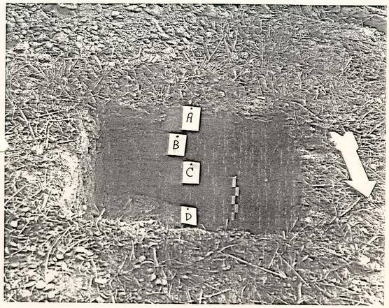 Figure 21. Profile of the south wall of Shovel Test Pit 1.
 Figure 22. Profile maps of the south and west walls of Shovel Test Pit 1.
Shovel Test Pit 2
Shovel Test Pit 2 was located in the same physical area as described under Shovel Test Pit 1. The test pit provenience was exactly 18.5 feet due east from Shovel Test Pit 1, at approximately the same elevation on the western side of the knoll (Figure 9).
HORIZON A
Horizon A (Figures 23 and 24) was composed of a black (10 YR 2/1) (Munsell Color 1975), sandy loam. A single nail was recovered (Appendix 1), although small brick fragments were noted in the soil horizon. This topsoil horizon is the same as described under Shovel Test Pit 1, Horizon A. As such, the layer appeared to represent a fill episode which post dated the late 19th to early 20th-century occupation on this corner of Block 34.
HORIZON B
Horizon B (Figures 23 and 24) consisted of a brownish yellow (10 YR 6/8) (Munsell Color 1975), sandy loam, with light red (10 YR 6/8) (Munsell Color 1975) and light gray (10 YR 7/20) (Munsell Color 1975) sandy loam mottles. No cultural material was gleaned from this horizon, although small brick fragments were not in the layer. This subsoil horizon was identical to that encountered in Shovel Test Pit 1, Horizon D. Therefore, this horizon most likely represents a superficially graded subsoil horizon that had been modified during the late 19th through early 20th-century occupation of this area.
In general, Shovel Test Pit 2 was indicative of extensive land modifications that had transpired in this particular portion of the project area, probably in the late 1800's or the early 1900's, when this portion of the block was occupied. Apparently, these alterations to the topography and soil stratigraphy erased all traces of the 18th-century components.
43
 Figure 23. Profile of the south wall of Shovel Test Pit 2.
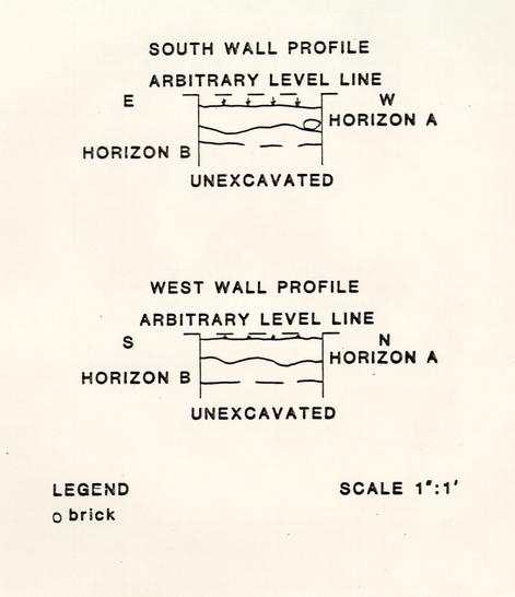 Figure 24. Profile maps of the south and west walls of Shovel Test Pit 2.
SUMMARY
In conclusion, the test excavations conducted at the site of the proposed Bus Turnaround 2 Project has provided us with valuable insight into the cultural resources that are present in the southeast corner of Block 34. On the eastern portion of the project area the remains of a late 19th to early 20th-century well and associated well-head, and builders trench, as well as a post hole were identified. The well (F-1a), and the well-head (F-1) were intact and appeared to retain their original structural integrity. These features are important in that they are prime examples of the types of construction techniques and materials that were used in well and well-head fabrication during the latter 19th and early 20th-century in Williamsburg (Noel Hume 1969:23). Of equal importance are the contents of the well. During this excavation we recovered numerous artifacts within the fill deposits in the well. As Noel Hume (1969) and others (Moran et al. 1982, Alexandrowicz n.d.) have noted, wells contain a variety of material culture that represent many facets of past lifeways. For instance, the fish bone and walnut artifacts recovered in this well fill provides us with a glimpse into the dietary pattern of the early 20th-century inhabitants of this property. In this particular case we are dealing with a specific Afro-American family, the Harris family. The feature complex may be instrumental in forming the data base for investigating the household consumption patterns and economics of this early 20th-century, Afro-American household in Williamsburg.
Two shovel test pits, located in the approximate area of the proposed curve in the turnaround produced negative evidence for intact 18th-century stratigraphy or cultural features. Although late 18th-century cultural material was recovered during these tests, the artifacts were found in disturbed contexts. On the other hand, these tests did confirm the late 19th and early 20th-century occupations in this corner of Block 34. These occupations, as well as neoteric landscaping activities have all contributed to the extensive disturbances in this area.
Finally, the area near Scotland Street appeared to be relatively undisturbed by modern occupations or landscaping activities. Eighteenth-century cultural materials were found in direct association with apparent undisturbed cultural strata. A possible cultural feature was identified. However, the exact nature and extent of this feature is unknown at this time. Future excavations are necessary to determine the precise spatial and temporal characteristics of this feature.
RECOMMENDATIONS FOR MITIGATION
The data generated by the test excavations in the vicinity of the second proposed bus turnaround project has yielded mixed results. In-situ cultural strata and features associated with the 18th through the early 20th-century occupations of this portion of Block 34 are located at both proposed intersections of the bus turnaround. Therefore, extreme care should be taken if grading and/or other earth moving operations are performed at those loci in order to avoid disturbing the integrity of the cultural phenomenon.
Modern disturbances, related to the late 19th through early 20th-century habitation and subsequent landscaping activities, in the vicinity of the proposed curve, have apparently eradicated all traces of previous occupations. Proposed modifications to the topography in this vicinity should not adversely affect pre-20th century cultural features and/or strata.
Finally, a comprehensive, archaeological monitoring operation (Alexandrowicz 1985c) should be undertaken during the proposed construction project. In the event that significant cultural resources are uncovered, a salvage program will be initiated at that time.
REFERENCES CITED
- 1985a
- Monitoring Activities: Palace Pasture Electric Line. Monthly Report on Archaeological Activities, February 1985. Ms. on file, Department of Archaeology, O.E.C., Colonial Williamsburg Foundation, Williamsburg.
- 1985b
- Rapid Projected Mapping: An Alternative Mapping Technique for the Archaeologist. Historical Archaeology 19(1) : 79-85.
- 1985
- c Archaeological Monitoring of Construction Projects in Colonial Williamsburg, VA. Paper presented at the 18th Meeting of the Society for Historical Archaeology, Boston.
- n.d.
- Recent Archaeological Investigations on the Camp Peary West Parcel, Colonial Williamsburg Foundation, Ms. on file, Department of Archaeology, O.E.C., Colonial Williamsburg Foundation, Williamsburg (in preparation).
- n.d.
- The Market Street Site District, Pittsburgh, Pennsylvania: A Case Study in Urban Archaeology. Unpublished M.A. Thesis, Department of Anthropology, University of Pittsburgh (in preparation).
- 1782
- Frenchman's Map. Map on file, Department of Archaeology, O.E.C., Colonial Williamsburg Foundation, Williamsburg.
- 1985
- Personal communication on faunal analysis Department of Archaeology, O.E.C., Colonial Williamsburg Foundation, Williamsburg.
- 1800
- Plan of the City of Williamsburg from the... Benj. Bucktrout 1800. Map on file, Department of Archaeology, O.E.C., Colonial Williamsburg Foundation, Williamsburg.
- 1985
- Plan of the proposed Bus Turnaround 2 project, Block 34. Map on file, Architecture Department, Colonial Williamsburg Foundation, Williamsburg. 48
- 1927
- Photograph showing the houses situated on Block 34. Negative No. 79-1409 on file, Audio-visual Department, Colonial Williamsburg Foundation, Williamsburg.
- n.d.
- Photograph showing the houses situated on Block 34 in the 1930's after the reconstruction of the Palace. Negative No. 79-1265 on file, Audio-visual Department, Colonial Williamsburg Foundation, Williamsburg.
- 1929
- Crutchfield Rent File 1929-1933. Archives Department, Colonial Williamsburg Foundation, Williamsburg.
- 1985
- Personal Communication. Williamsburg.
- 1985
- Bus Turnaround, Blocks 34 and 28: Archaeological Briefing. Ms. on file, Department of Archaeology, O.E.C., Colonial Williamsburg Foundation, Williamsburg.
- 1984
- Bus Turnaround Briefing: Blocks 28 and 34. Ms. on file, Department of Archaeology, O.E.C., Colonial Williamsburg Foundation, Williamsburg.
- 1985
- Personal Communication. Colonial Williamsburg Foundation, Williamsburg.
- 1940
- Harris House General File. Archives Department, Colonial Williamsburg Foundation, Williamsburg.
- 1985
- Personal Communication. Colonial Williamsburg Foundation. Williamsburg.
- 1984
- Phase II Archaeological Testing of the Proposed Second Street Extension, York County and Williamsburg, Virginia. Ms. on file, Department of Archaeology, O.E.C., Colonial Williamsburg Foundation, Williamsburg. 49
- n.d.
- Phase I Archaeological Reconnaissance Survey of The Proposed Route 199 Extension Corridor. Ms. on file, Department of Archaeology, O.E.C., Colonial Williamsburg Foundation, Williamsburg (in preparation).
- 1942
- Map Showing Approximate Location of 17th Century Horse Path Which Went Through Williamsburg Prior To 1699 When The Area Was Known As Middle Plantation. Map on file, Architecture Department, Colonial Williamsburg Foundation, Williamsburg.
- 1947a
- Archaeological Report: Block 34, Area A. Ms. on file, Department of Archaeology, O.E.C. Colonial Williamsburg Foundation, Williamsburg.
- 1947b
- Archaeological Survey of Foundation, S.E. Corner of Block 34, Williamsburg, Va. Map on file, Department of Archaeology, O.E.C., Colonial Williamsburg Foundation, Williamsburg.
- 1947c
- Photograph W-98. Photograph of the 18th-century chimney foundation located in the 1947 archaeological excavations. Photo on file, Department of Archaeology, O.E.C., Colonial Williamsburg Foundation, Williamsburg.
- 1983
- Terminus Post Quem dates for cataloging artifacts excavated by the Office of Excavation and Conservation. Ms. on file, Department of Archaeology, O.E.C., Colonial Williamsburg Foundation, Williamsburg.
- 1982
- Archaeological Investigations at the Narbonne House: Salem Maritime National Historic Site, Massachusetts. Cultural Resource Management Study No. 6. National Park Service, Boston.
- 1975
- Munsell Soil Color Charts. Kollmorgan Corporation, Baltimore.
- 1968
- Nail Chronology As An Aid To Dating Old Buildings. American Association for State and Local History Technical Leaflet 48, History News 24(11). 50
- 1969
- The Wells of Williamsburg: Colonial Time Capsules. Colonial Williamsburg Archaeological Series No. 4.
- 1985
- Archaeological Briefing: Bus Turnaround, Block 34. Ms. on file, Department of Archaeology, O.E.C., Colonial Williamsburg Foundation, Williamsburg.
- 1985
- Personal Communication. Colonial Williamsburg Foundation, Williamsburg.
- 1929
- Property Plat Block No. 34, Restoration Survey Williamsburg, Virginia. Map on file, Department of Archaeology, O.E.C., Colonial Williamsburg Foundation, Williamsburg.
APPENDIX 1: ARTIFACT INVENTORY
TEST EXCAVATION UNITS 1 AND 3
Test Excavation Unit 1
| ARTIFACT TYPE | # SPECIMENS | TERMINUS POST QUEM |
|---|---|---|
| cinders | 2 | not applicable |
| bone- fish, vertebra centrum, (Teleostei sp.) (Bowen 1985, personal communication) | 1 | not applicable |
| coal | 3 | not applicable |
| macadam pavement | 2 | not applicable |
| brick | 1 | not applicable |
| bog iron | 1 | not applicable |
| gravel | 8 | not applicable |
| shell- oyster | 3 | not applicable |
| nail- hand-wrought | 1 | 17th-c. (Nelson 1968) |
| nail- wire | 5 | 1880 (Nelson 1968) |
| ceramic- pearlware, plate, base and foot, 1 vessel | 2 | 1779 (Miller 1983) |
| ceramic- unglazed redware, flower pot, rim, 1 vessel | 1 | not applicable |
| glass- aqua, window | 1 | not applicable |
| glass- clear, BIM, bottle | 1 | not applicable |
| glass- clear, BIM, drinking glass or mug | 1 | not applicable |
| glass- amber, BIM, bottle embossed "...NC CO..." | 1 | not applicable |
| brick fragments | 18 | not applicable |
| cinder | 3 | not applicable |
| shell- oyster | 1 | not applicable |
| shell- scallop | 1 | not applicable |
| shell- marl | 19 | not applicable |
| gravel | 1 | not applicable |
| ceramic- whiteware, plate, base with foot, 1 vessel | 1 | 1820 (Miller 1983) |
| ceramic- whiteware, plate, rim, 1 vessel | 1 | 1820 (Miller 1983) |
| glass- aqua, BIM, bottle, one fragment embossed "...S" | 2 | not applicable |
| 52 | ||
| glass- aqua, BIM, bottle | 1 | not applicable |
| sterile | - | - | - |
Test Excavation Unit 3
| bricks | 4 | not applicable |
| concrete (with gravel) | 6 | not applicable |
| macadam pavement | 2 | not applicable |
| clinker | 4 | not applicable |
| cinders | 7 | not applicable |
| coal | 6 | not applicable |
| mortar (gravel) | 2 | not applicable |
| gravel | 15 | not applicable |
| bog iron | 1 | not applicable |
| wire- iron | 1 | not applicable |
| nails- wire | 3 | 1880 (Nelson 1968) |
| shell- oyster | 9 | not applicable |
| shell-marl | 16 | not applicable |
| ceramic- whiteware, plate, base with foot, 1 vessel | 1 | 1820 (Miller 1983) |
| ceramic- redware, form (?), body, glazed interior/ exterior, 1 vessel | 1 | not applicable |
| ceramic- redware, crock, rim, glazed interior/exterior, 1 vessel | 1 | not applicable |
| glass- clear, BIM, rim and body, | 7 | not applicable |
| glass- clear, BIM, body | 1 | not applicable |
| glass- aqua, BIM, body | 1 | not applicable |
| glass- olive green, free-blown, body | 1 | not applicable |
| brick fragments | 5 | not applicable |
| shell- oyster | 3 | not applicable |
| shell- marl | 28 | not applicable |
| cinder | 10 | not applicable |
| clinker | 3 | not applicable |
| coal | 3 | not applicable |
| gravel | 6 | not applicable |
| 53 | ||
| mortar (sand and gravel) | 1 | not applicable |
| nail- hand-wrought | 1 | 17th century |
| nail- machine cut, | 2 | 1790 (Nelson 1968) |
| hand-headed | ||
| nail- wire | 3 | 1880 (Nelson 1968) |
| ceramic- whiteware, form (?) | 1 | 1820 (Miller 1983) |
| glass- aqua, window, 1 pane | 2 | not applicable |
| glass- aqua, window | 1 | not applicable |
| glass- light aqua, window | 1 | not applicable |
| glass- clear, BIM, body | 1 | not applicable |
| Brick with sand mortar | 1 | ca. 19th century |
| shell- marl | 20 | not applicable |
| nail- wire | 1 | 1880 (Nelson 1968) |
| brick fragments | 4 | not applicable |
| charcoal | 2 | not applicable |
| gravel | 1 | not applicable |
| ceramic- porcelain, plate, rim with liquid gold decoration | 1 | 1880 (Miller 1983) |
| glass- clear, BIM, body | 1 | not applicable |
| glass- aqua, BIM, body | 1 | not applicable |
| bone- fish, preoperculum, (Sciaenidae sp.) "Drum family" (Bowen 1985, personal communication) | 1 | not applicable |
| brick fragments | 1 | not applicable |
| gravel | 1 | not applicable |
| shell- marl | 2 | not applicable |
| cinders | 2 | not applicable |
| brick fragments | 9 | not applicable |
| mortar- shell | 1 | 18th century |
| mortar- sand/gravel | 1 | 19th century |
| concrete | 1 | not applicable |
| gravel | 13 | not applicable |
| 54 | ||
| clinker | 3 | not applicable |
| cinders | 2 | not applicable |
| charcoal | 1 | not applicable |
| coal | 3 | not applicable |
| shell - marl | 9 | not applicable |
| bone- (species ?) | 1 | not applicable |
| nails- wire | 3 | 1880 (Nelson 1968) |
| glass- aqua, window | 1 | not applicable |
| glass- clear, window | 1 | not applicable |
| glass- clear, BIM, base | 1 | not applicable |
| glass- clear, BIM, body | 2 | not applicable |
| brick fragments | 5 | not applicable |
| concrete | 5 | not applicable |
| cinders | 5 | not applicable |
| charcoal | 1 | not applicable |
| slate | 1 | not applicable |
| gravel | 7 | not applicable |
| shell- marl | 9 | not applicable |
| clinker | 1 | not applicable |
| nails- machine-cut | 2 | 1830 (Nelson 1968) |
| ceramic- creamware, form (?) | 1 | 1762 (Miller 1983) |
| glass- pink, pressed, body, "Depression Glass" | 1 | 1920's to 1930's |
| brick fragment | 1 | not applicable |
| bog iron | 2 | not applicable |
| gravel | 5 | not applicable |
| concrete | 2 | not applicable |
| clinker | 6 | not applicable |
| cinder | 6 | not applicable |
| coal | 1 | not applicable |
| charcoal | 1 | not applicable |
| mortar- sand | 1 | 19th century |
| mortar- shell | 1 | 18th century |
| nail- indeterminate | 3 | not applicable |
| nail- machine-cut | 1 | 1830 (Nelson 1968) |
| nail- wire | 4 | 1880 (Nelson 1968) |
| shell- snail | 1 | not applicable |
| shell- marl | 11 | not applicable |
| walnut (Juglans nigra) (Montgomery 1977) | 5 | not applicable |
| 55 | ||
| bone- fish, right maxillary (Micropogon undulatus) "Croaker" (Bowen 1985, personal communication) | 1 | not applicable |
| ceramic- delft, form (?), body sherd | 1 | 18th century |
| ceramic- porcelain, form (?), body sherd | 1 | 19th century |
| glass- clear, BIM, bottle | 1 | not applicable |
TEST EXCAVATION UNIT 2
| brick fragment | 1 | not applicable |
| gravel | 2 | not applicable |
| nail- indeterminate | 1 | not applicable |
| nail- machine-cut, with handmade head | 1 | 1790 (Nelson 1968) |
| ceramic- pearlware, form (?) body sherd | 1 | 1779 (Miller 1983) |
| glass- aqua, window | 1 | not applicable |
| glass- olive green, blown-molded, case bottle | 1 | 1730 (Miller 1983) |
| glass- olive green, hand blown, bottle | 1 | 18th-19th century |
| glass- olive green, hand blown, bottle, 2 vessels | 3 | 18th-19th century |
| nail- hand-wrought | 1 | 17th century |
| kaolin pipe stem | 1 | 18th century |
| ceramic- pearlware, plate | 1 | 1780 (Miller 1983) |
| blue shell edge rim | ||
| ceramic- creamware, form (?) | 1 | 1762 (Miller 1983) |
| glass- olive green, free-blown, bottle | 1 | 18th century |
| sterile | - | - | - |
SHOVEL TEST PIT 1
| nail- wire | 1 | 1880 (Nelson 1968) |
| glass- amber, BIM, bottle, body sherd | 1 | not applicable |
| bone- mammal, 2nd and 3rd carple, Bos taurus, cow (Bowen 1985, personal communication) | 1 | not applicable |
| bone- mammal, unidentified | 6 | not applicable |
| bone- bird, unidentified | 2 | not applicable |
| nail- wire | 8 | 1880 (Nelson 1968) |
| nail- machine-cut | 2 | 1830 (Nelson 1968) |
| nail- machine-cut with handmade head. | 1 | 1790 (Nelson 1968) |
| nail- unidentified | 2 | not applicable |
| ceramic- pearlware, form (?), underglaze transfer print, body sherd | 1 | 1787 (Miller 1983) |
| ceramic- whiteware, plate, makers mark fragment: | 1 | 20th century |
| "...A" | ||
| "...NA" | ||
| "43" base sherd | ||
| ceramic- ironstone, plate, base sherd | 1 | 1845 (Miller 1983) |
| gravel | 1 | not applicable |
| nail- machine-cut with with handmade head | 2 | 1790 (Nelson 1968) |
| ceramic- pearlware, plate, blue shell edge rim | 1 | 1780 (Nelson 1968) |
| ceramic- white ware, cup overglaze transfer print, body sherd | 1 | 1820 (Miller 1983) |
| glass- olive green, free basal fragments | 2 | 18th century |
SHOVEL TEST PIT 2
| nail - wire | 1 | 1880 (Nelson 1968) |
| sterile | - | - | - |